drive by wire ITB system
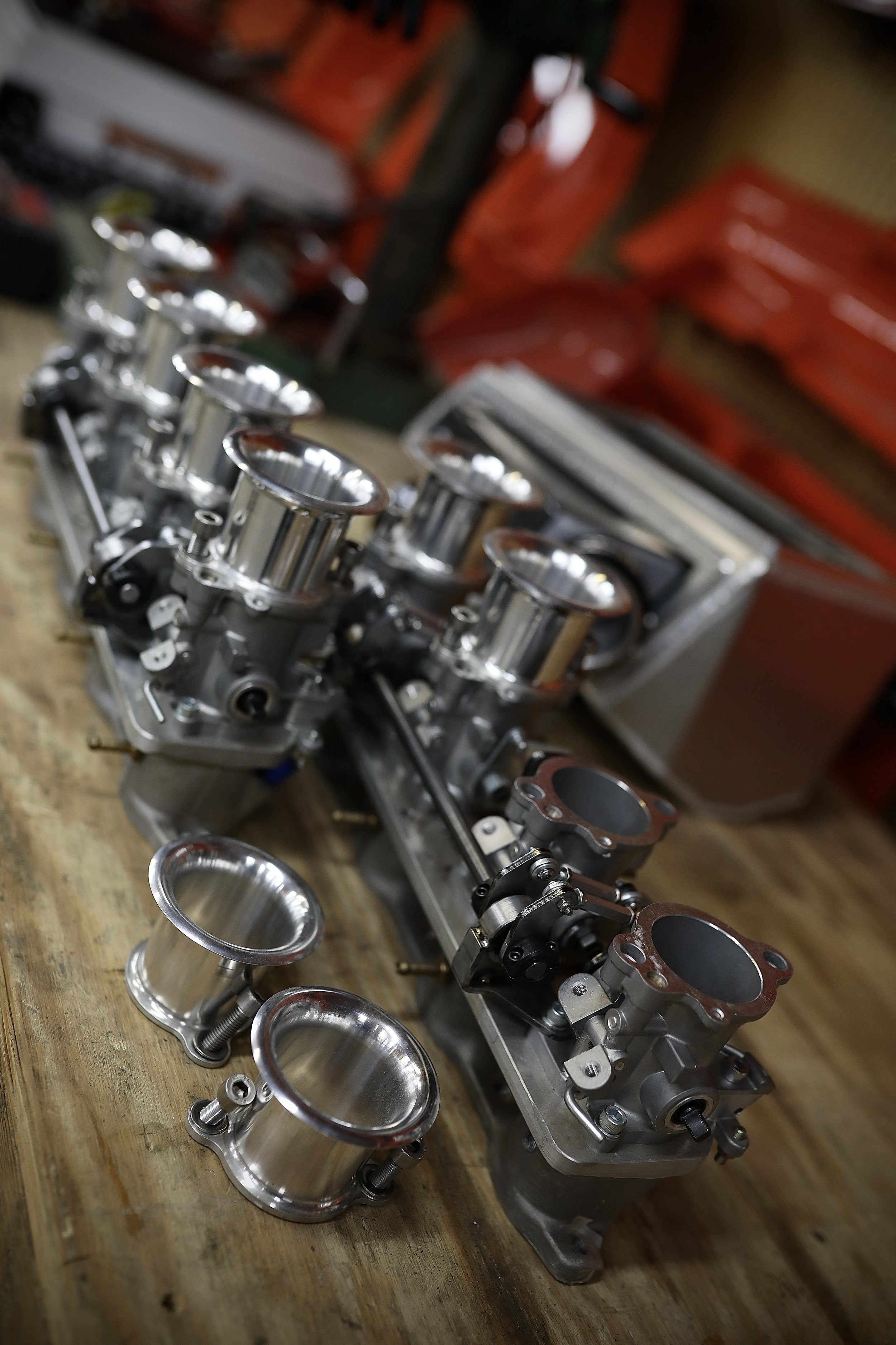
Running individual throttle bodies on the 1UZFE V8 engine caused some foreseeable tunability issues with the standalone engine management, mainly due to the fact that the throttle kit I was using was for manual cable operated throttle. Knowing that I would like to retrofit this system to go drive by wire, I had challenges to overcome. One of the hardest things to overcome with a cable driven ITB system is idle control as there is no idle air bypass valve that can be plumbed into the system. Operating the system by drive by wire eliminates the need for any idle bypass as the throttle blade positions can be directly controlled by the ECU to hold any programmed idle speed, along with other features such as cruise control and traction control which would be impossible to implement with a cable operated system.
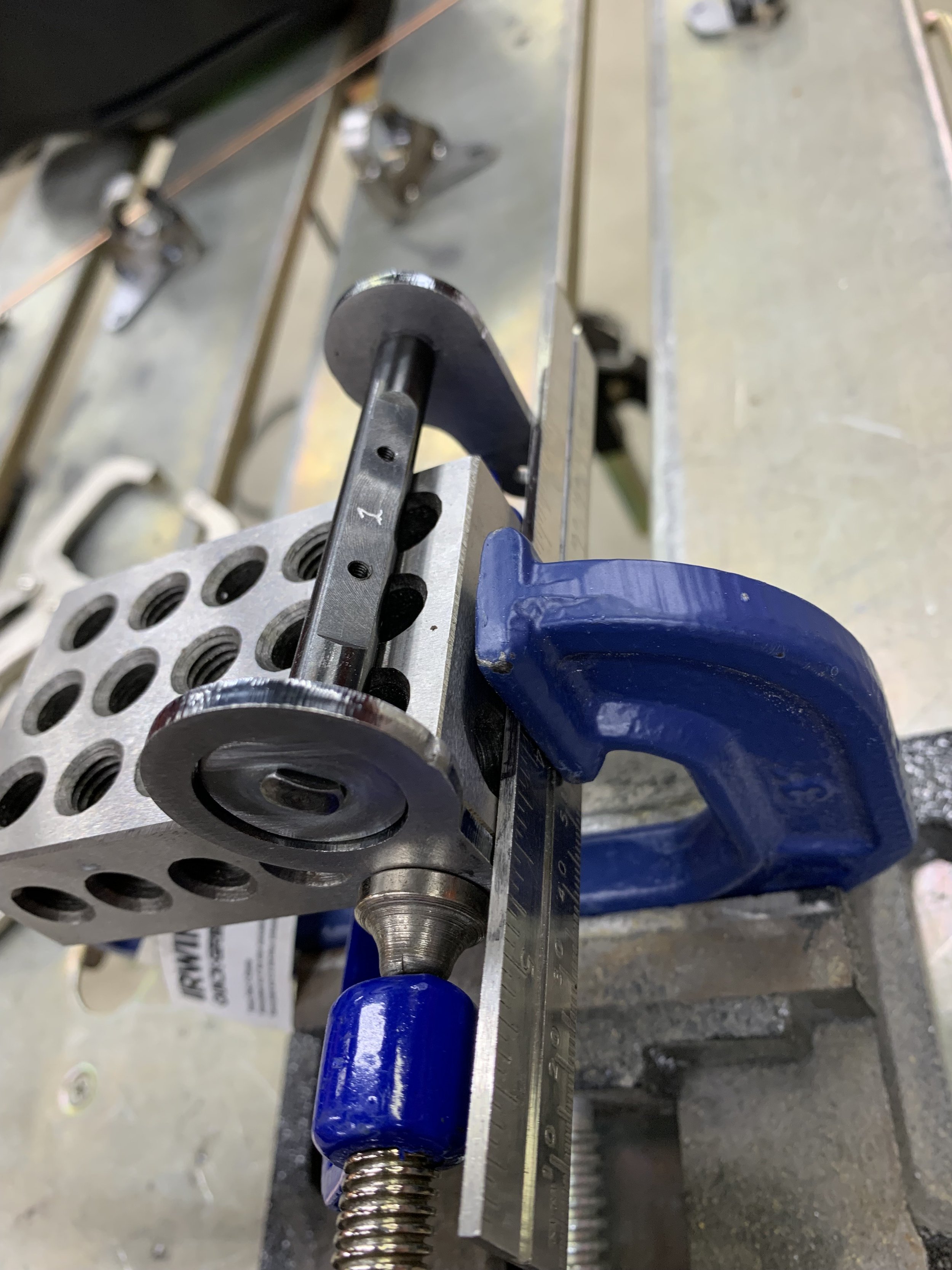
Starting with a standard LS3 drive by wire throttle body, I was able to design an actuator arm system around the throttle body’s center pivot while removing the unneeded throttle butterfly and inlet area. Manually milling the throttle casting and laser cutting a new armature system to attach to the throttle pivot, I now had a great standalone throttle actuator that fit just between the two banks of ITB’s. Programming the electronic throttle to the ITB’s using a digitally designed and laser cut test bench, it quickly became apparent that the LS3’s drive by wire motor was having to run near 100% duty cycle just to slowly operate all 8 throttles with no real resistance, which posed an issue.
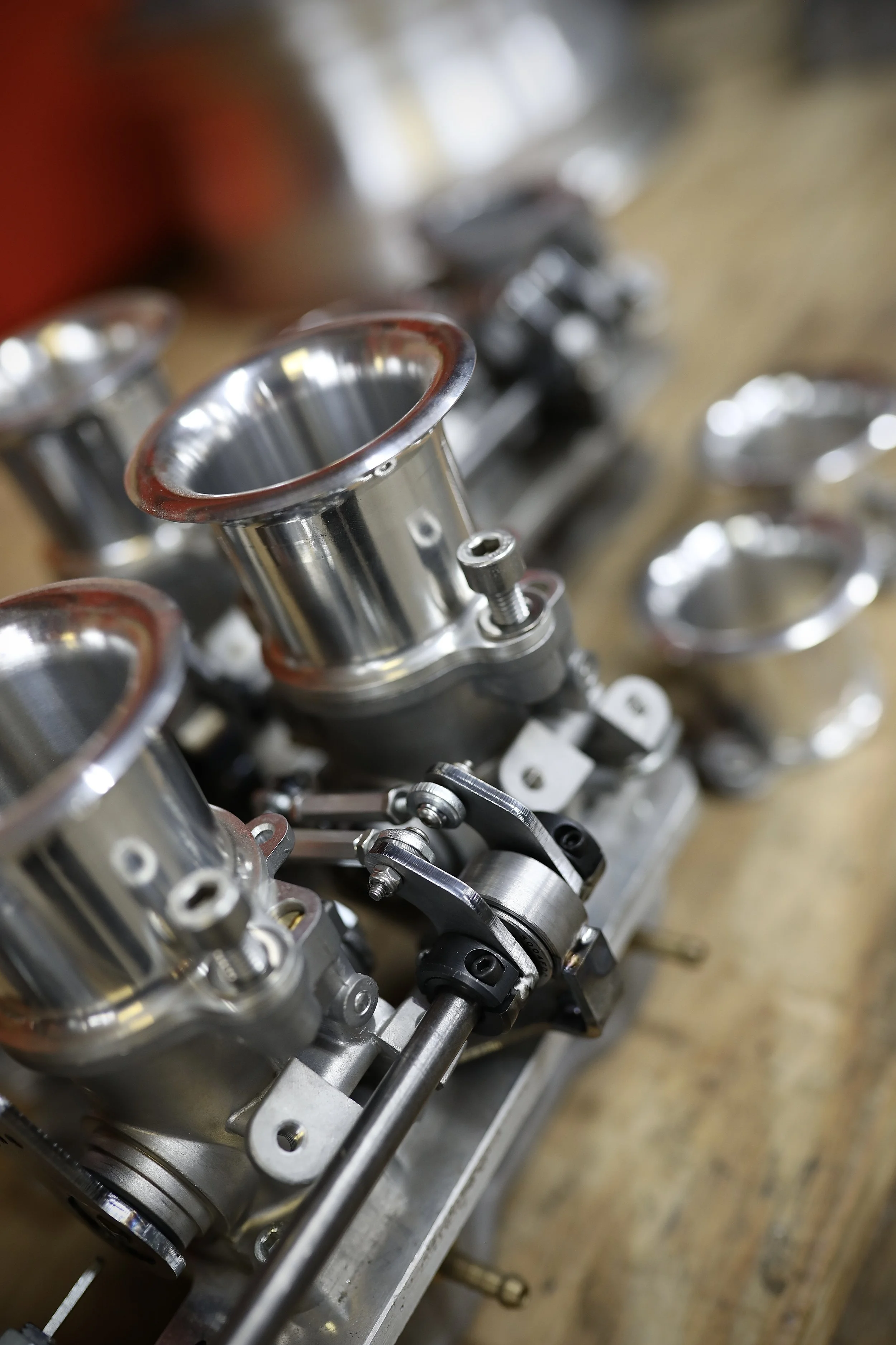
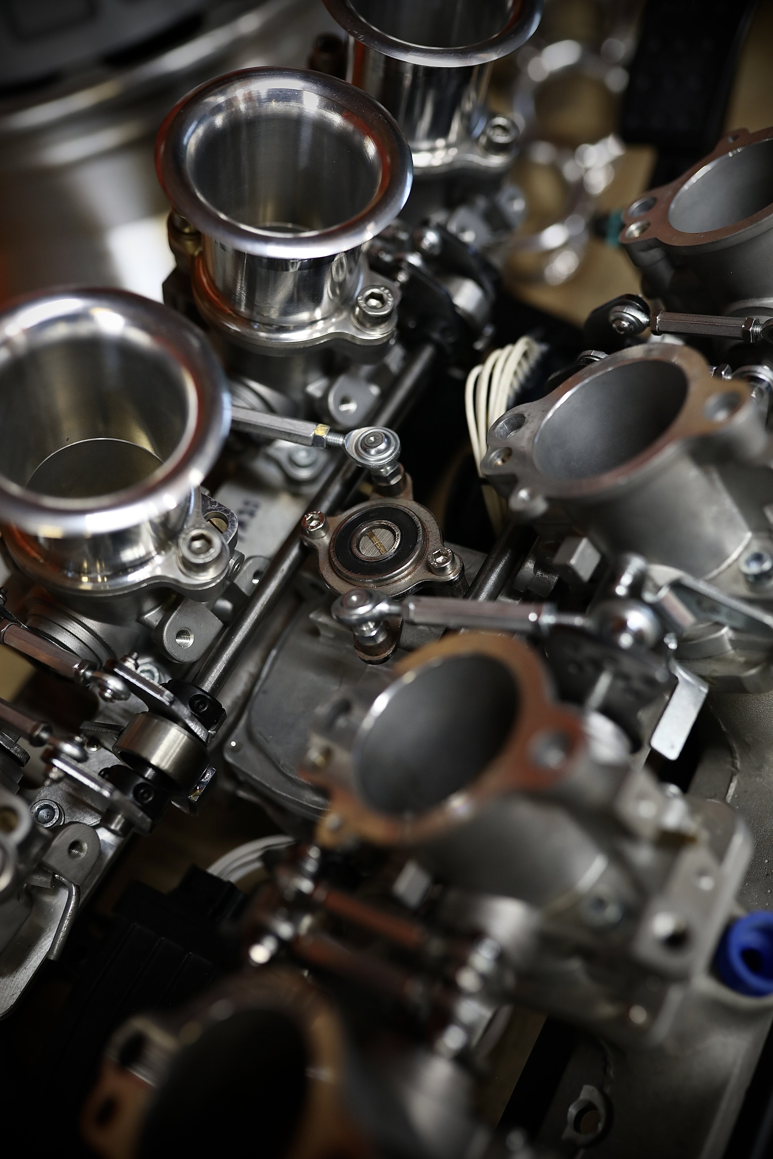
A closer look at the ITB kit being used showed that all the linkages at each throttle body were crudely pinch-connected to one another with many torsion springs for return. The sloppy and cheap linkage sets coupled with all the springs meant to return the cable operated system was causing an unnecessary amount of actuation force to be needed at each bank. I decided to clean slate all the linkages at each throttle, having each linkage properly actuated by adjustable heim jointed arms that were driven from common bank ball bearing pivots on each side. I needed to calculate the amount of throw needed at each throttle for complete operation, along with lever ratio used at both the throttles and drive motor to equate the least force needed while having the highest resolution possible.
New laser cut actuator arms were either bolted or welded in to replace the old sloppy units, and the adjustable heim actuators were set to a normalized zero across all 8 throttles. The new system operated buttery smooth with very little effort to manually operate, which was proven effective as programming the drive motor to the throttles now only needed 60% duty cycle at the fastest and most rapid operation.