1UZFE ITB CARBON INTAKES
There have been a handful of different intake designs I have run over the years for this build, but zoning in on the ideal final version has always been a full carbon split plenum. It always felt a bit too far out of reach for my capabilities and tool access to do an intake with carbon bodies, but as my skills and comfortability grew both with machining and carbon work it became a more approachable project to tackle. Focusing on the stock hood being able to close over top of the new design, there was also a large effort to optimize the plenum floor and volume shapes for ideal and balanced air flow into each runner. Using dynamic flow modeling on various different shapes of all the intake parts, the final forms shown proved to provide the best balance given the space constraints to design around.
The billet O-ring sealed base was designed to bolt onto the existing ITB structure that was already in place, and all milling was programmed in Fusion 360 CAM to be milled from solid aluminum on my Shapeoko 3-axis CNC mill. The base profiles, clamping rings that sandwich clamp the carbon plenums to the base, and even the milled thread profiles for the Vibrant wiggins clamps at the plenum inlets were made all in house.
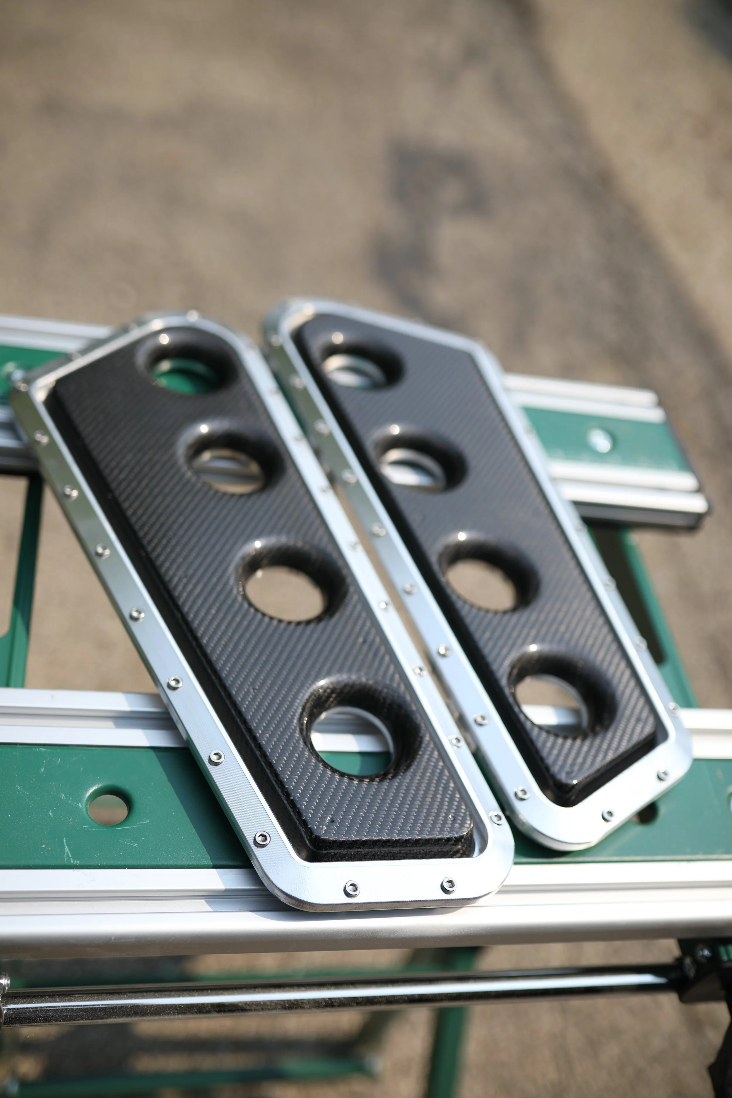
The carbon plenum floors were proven to have the best air flow balance into the runners with large radiused bell profiles, which then had male bucks machined from MDF and body worked into plugs to make fiberglass molds. The same process was used on the upper plenums, with the exception that the plugs for the plenum shapes were first 3D printed and not machined. All parts were then resin infused from thick carbon laminate using high temp epoxy from the newly developed molds.
All carbon parts were trimmed and fit to their complimentary billet parts, and finally received UV clear coat before final assembly.